
Direct answer: Radiant tubes transfer heat into a heat-treatment furnace through a burner or heating system. Selection depends on the furnace layout, burner interface, dimensions, atmosphere, operating cycle and failure history. ECOOSUN can review a drawing or used sample for a project-specific replacement.
A radiant tube with an open crack may also have a bowed leg, a thin burner-side wall and a support that no longer carries its share of the weight. Calling the event “oxidation” or “creep” too early can hide that interaction. The crack is the final visible event; the investigation must reconstruct what happened before it opened.
The most useful starting point is a damage map tied to furnace position. Mark the burner end, exhaust end, top, bottom, supports and welds before the tube is moved. Then separate three questions: Where has metal been lost? Where has the geometry changed? Where did cracking begin?
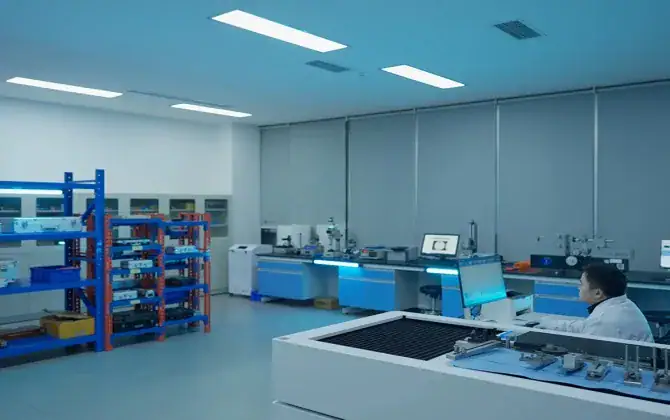
Orientation marks and an as-removed photograph preserve the relationship between surface condition, burner position and supports.
The Evidence Map Comes Before the Mechanism Name
Photograph the tube in place and again after removal. Record furnace zone, installation date, cycle pattern, atmosphere, burner settings, shutdown history and any earlier repair. Compare it with an adjacent tube that remains in service; that reference can reveal whether the failed tube saw a local condition or a broader furnace environment.
Use a repeatable measurement grid rather than measuring only beside the opening:
- wall thickness around the circumference and along both legs;
- outside diameter or ovality at the same stations;
- straightness relative to known support points;
- crack origin, direction and distance from a bend, weld or restraint;
- scale, deposits and discoloration on internal and external surfaces;
- support contact, clearance and freedom for thermal movement.
A local hot patch near the burner, broad bowing between supports and a crack beside a rigid joint are different evidence patterns even when they occur on the same tube.
Oxidation: Ask Whether the Surface Film Is Still Protective
The heat-resistant-steel reference in the supplied library explains why oxide-film behavior matters. Its section on chemical corrosion describes oxidation as a reaction that first forms a surface film. Whether that film slows further attack depends on properties including continuity, stability and adhesion. The same source explains that dense chromium-containing oxides can improve oxidation resistance.
This gives the inspection a concrete purpose. Do not record only “heavy scale.” Determine whether scale is adherent or repeatedly spalled, and whether underlying wall loss is uniform or sharply localized. Repeated loss of a protective film exposes fresh metal and can turn a surface reaction into continuing section loss.
Map the pattern against furnace hardware:
- burner-end concentration calls for a flame-pattern and tube-metal-temperature review;
- one-sided loss calls for comparison with gas flow, deposits and shielding by nearby parts;
- loss at a support calls for contact, rubbing and local temperature review;
- widespread loss calls for review of the alloy, atmosphere, exposure and cycle together.
The furnace setpoint is not a substitute for measured or otherwise verified tube-metal conditions. It cannot show a local hot spot created by flame impingement or combustion imbalance.
Oxidation Resistance Is Not the Same as Hot Load-Bearing Strength
One of the most important points in the source book appears in its classification of heat-resistant steel. It distinguishes steel selected mainly for oxidation resistance from heat-strength steel, which must combine oxidation resistance with strength at elevated temperature. That distinction matters directly to a radiant tube: the surface must resist the environment while the tube also carries its own weight across the support arrangement.
An alloy change based only on scale appearance can therefore miss the deformation problem. Conversely, selecting for hot strength without checking atmosphere compatibility can leave the wall vulnerable. The heat-resistant alloy selection guide expands this material-versus-duty distinction without giving a universal service-temperature promise.
Bowing, Ovality and Bulging: Reconstruct the Stress
Time at temperature under stress can produce progressive deformation. For a radiant tube, stress may come from self-weight, unsupported span, attached hardware, deposits, misaligned supports or restraint as the tube expands. The evidence is geometric: a change in straightness, diameter or local shape that can be located relative to the supports and thermal pattern.
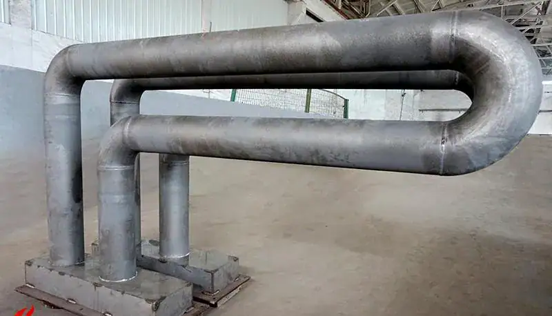
On a U-tube, measure both legs at matching stations and relate any bow or ovality to bends and supports.
Do not infer the cause from a single overall straightness reading. A smooth bow between supports suggests a different load path from a local bulge beside a hot zone. A displaced support can concentrate bending even when the alloy chemistry is correct. Deposits can add weight and change heat transfer at the same time.
If creep damage is suspected, laboratory examination and the actual time-temperature-stress history may be needed. The article does not assign a remaining life from appearance or from a generic online percentage.
Cracking at Bends, Welds and Restraints
Heating and cooling force the tube to expand and contract. Bends, welded transitions, flanges and rigid supports can concentrate strain, especially when neighboring sections do not heat at the same rate. A crack at one of these features is a prompt to examine geometry and restraint, not automatic proof of thermal fatigue.
Before cleaning, note whether the opening is oxidized inside or appears fresh. Establish the apparent origin rather than recording only total length. Look for repeated damage at the same furnace position and compare it with cycle changes, emergency shutdowns or rapid cooling events.
A repair weld restores local continuity but may not remove the cause. If the same joint remains restrained, the wall is thin beyond the repair, or the surrounding material has changed condition, a new crack can start beside the repaired area.
Carbon-Rich Atmospheres Require Verification, Not Guesswork
In carbon-rich service, near-surface material changes may reduce tolerance for thermal strain or repair. Visual appearance alone does not prove carburization. Review atmosphere and leak records, then use chemistry, hardness traverses or metallography across the wall when the distinction affects the repair or replacement decision.
Keep the sampling orientation. A section from the burner-facing surface should not be mixed with one from the shielded side, and a damaged sample should be compared with a reference location. Report whether the finding is local or extends through a substantial part of the wall.
Burner Conditions Can Defeat a Correct Material Specification
Review burner alignment, flame length, firing rate, fuel-air control, pressure and deposits inside the tube. A localized hot zone can accelerate surface reaction, reduce wall section and increase deformation together. If several tubes fail at the same furnace position while equivalent tubes elsewhere remain sound, that positional evidence deserves priority.
The sequence matters. Correct burner or support problems before assuming that a nominally “higher” alloy will solve them. Otherwise the replacement may reproduce the same thermal map with a more expensive material.
Fabrication and Casting Details Still Matter
Radiant-tube assemblies may combine cast bends, straight sections, flanges and welded joints. Fit-up, alignment, joint preparation, filler selection, transition geometry and specified inspection influence local behavior. The supplied source book also notes that alloy composition affects casting fluidity and defect tendency, reinforcing the need to treat material selection and manufacturability together rather than independently.
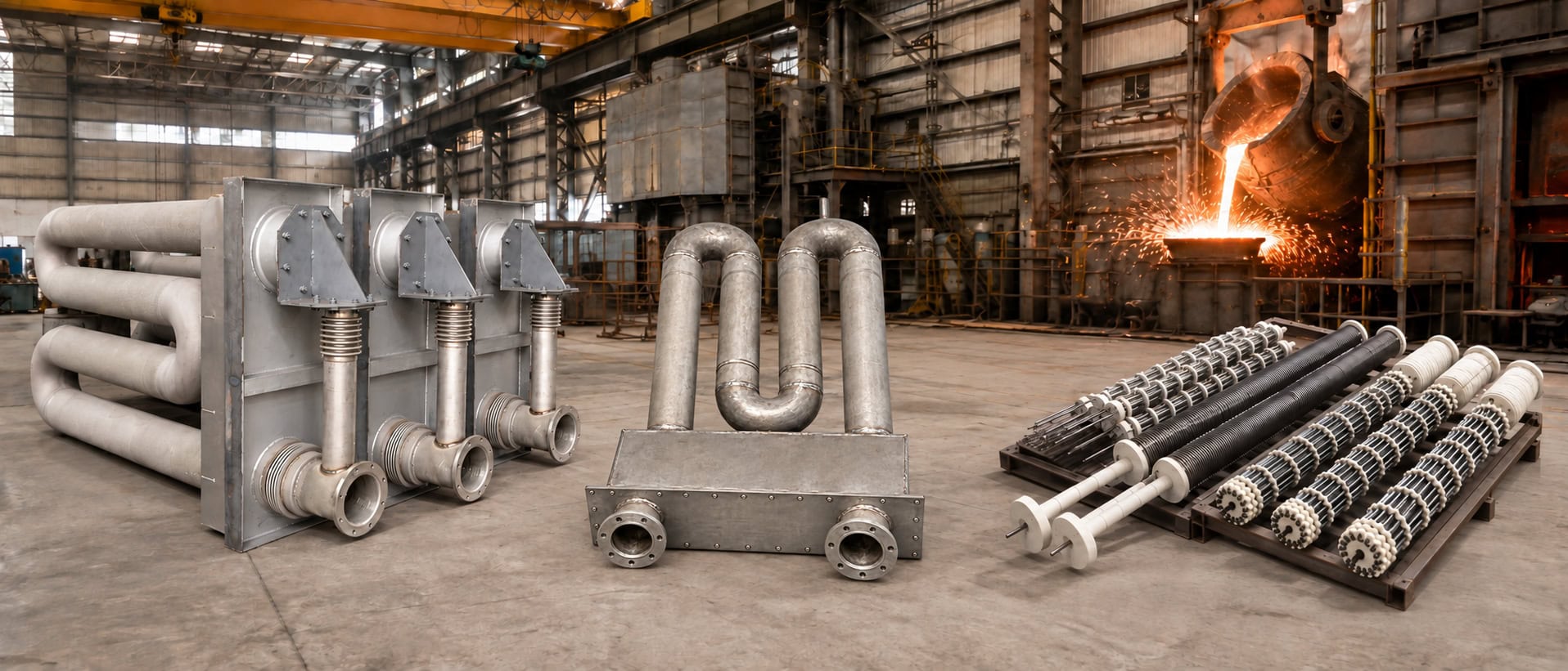
Joint locations, heavy-to-thin transitions and flange restraints should be shown in the inspection record and replacement drawing.
For a replacement, specify joint locations, machined interfaces, alignment, leakage requirements and inspection areas. The radiant tubes page shows typical component forms, while custom heat-resistant alloy parts covers non-standard castings and assemblies.
Decide Among Repair, Replacement and Controlled Redesign
A local repair may be reasonable when damage is limited, remaining wall and geometry are acceptable, and an approved procedure exists for the material and condition. Replacement becomes more credible when loss extends beyond the visible opening, straightness is no longer acceptable, degradation is broad, or the same location has failed repeatedly.
When changing the design, alter variables deliberately. Record any revised alloy, wall, transition, support, joint or burner setting. Mark the installation date and furnace position. Without that record, the next service result cannot tell the plant which change helped.
Dimensional and material records turn the replacement into a controlled comparison rather than another isolated trial.
Build Inspection Intervals From Repeatable Measurements
During planned shutdowns, measure the same wall-thickness and geometry stations. Trend local loss, ovality, straightness, support condition and burner observations together. A stable average can still hide an accelerating burner-end hot spot, so keep location data instead of reducing the inspection to one number.
Retirement criteria must come from component design, operating risk and the applicable engineering requirements. Trending supports planned decisions; it does not create a universal safe remaining life.
For a technical review, send the as-removed photographs, measurement grid, drawing, alloy designation, atmosphere, cycle, burner arrangement, supports and inspection requirements through the ECOOSUN contact page. Related replacement components are summarized under heat-treatment furnace parts.
Reference Boundary
The material principles in this article are drawn from Cast Steel and Cast Superalloys and Their Melting (`铸钢和铸造高温合金及其熔炼.pdf`), especially PDF pages 60, 64 and 65 on oxide-film protection, alloying effects and the distinction between oxidation-resistant and heat-strength steels; pages 69 and 74 were reviewed for alloy and casting context. These pages do not provide ECOOSUN radiant-tube service-life data. Claims about a specific failed tube still require its operating record, dimensional evidence and, where necessary, laboratory examination.
If a failed assembly includes suitable precision-cast fittings, Silica Sol Investment Casting may be assessed after the failure location, atmosphere and temperature profile are understood.
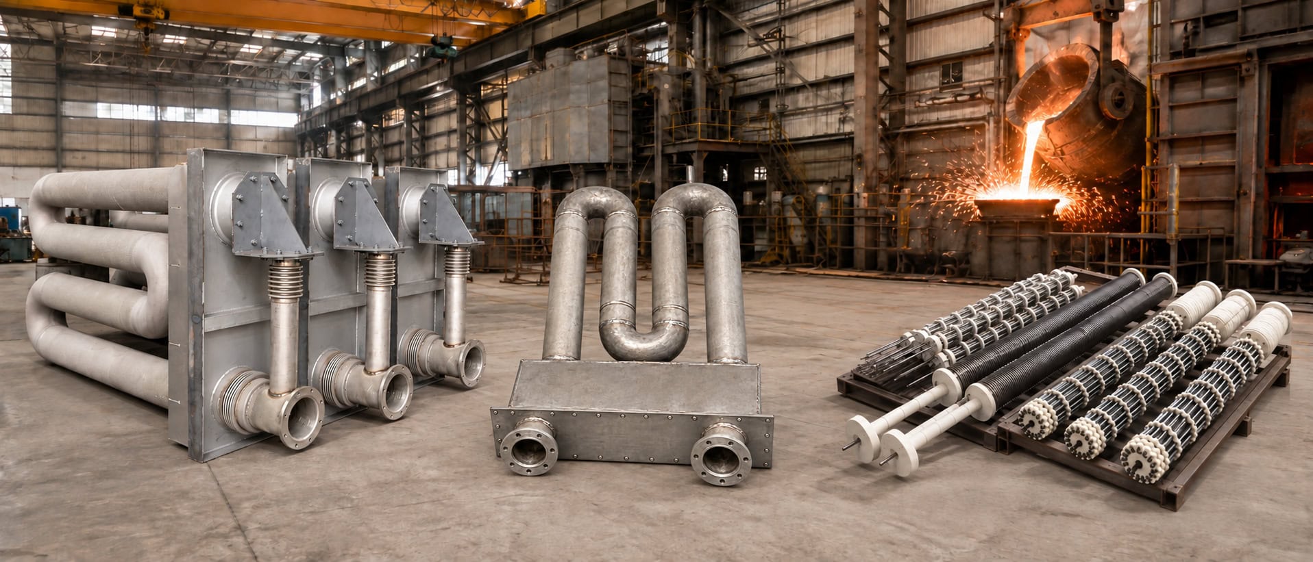
Production context: The component reference should be read together with the manufacturing and inspection context behind the furnace application.

FAQ
What should a buyer confirm for a radiant tube requirement?
Confirm the drawing or used sample, key dimensions and interfaces, furnace type and clearance, load, operating cycle, failure evidence and inspection requirements. Final acceptance criteria should be agreed for the specific project.
Can ECOOSUN review a custom radiant tube requirement?
Yes. ECOOSUN can review a customer drawing or used sample and discuss casting, laboratory and inspection requirements for a custom furnace-component project. Suitability and final scope are confirmed from the supplied information.
Related Radiant Tube Resources
Use these technical guides when specifying, inspecting or replacing radiant tubes for an industrial furnace:
- Radiant Tubes for Annealing and Heat-Treatment Furnaces
- Straight, U-Type or W-Type Radiant Tubes
- Radiant Tube Failure: Cracking, Sagging and Oxidation
- Radiant Tube Installation and Connection Inspection Guide
- Industrial Furnace Radiant Tubes: Material and Service Life
Related ECOOSUN Products
Information for a Faster Quotation
Provide alloy grade or service conditions, straight/U/W form, tube dimensions, burner and connection details, operating temperature, furnace zone, quantity, drawing or used sample, and inspection requirements.
Request a Custom Quote · Send Your Drawing · WhatsApp ECOOSUN


 +44 7419 144346